
The controls stack is where the most expensive misunderstandings in BESS development originate. Not because the technology is immature, but because the boundaries between systems are poorly defined in contracts and poorly tested before commercial operation.
Most content about BESS controls is written by equipment vendors or controls companies selling their own products. The developer’s problem is different. The developer selects the OEM, writes the supply agreement’s technical exhibits, defines the EPC scope, selects or approves the energy management system and dispatch optimizer, engages the scheduling coordinator, and owns the commissioning acceptance. Every one of those decisions shapes the controls architecture, and a bad decision at procurement creates a commissioning problem that no amount of field engineering can fix cheaply.
This article is an attempt to map the full controls stack from cell to ISO, drawing the boundaries between systems, identifying the decisions the developer has to make, and flagging where integration risk concentrates in our experience. The perspective throughout is the developer’s. We do not design controls systems. We understand the role each component plays, know where the boundaries are, and manage the scope and execution of the parties responsible for each layer.
One note before we begin: “controls” in the BESS context is a broader term than most people realize. It encompasses real-time safety protection, commercial dispatch optimization, market bidding, settlement metering, and cybersecurity. These functions belong to different vendors, different contracts, and different timescales, but they must all be coordinated from commercial operation through Year 20.
The Full Stack at a Glance
The controls stack is not one system. It is eight or more distinct systems, built by different vendors, speaking different protocols, operating at different speeds, governed by different contracts, and maintained by different parties. The table below maps them from the cell level up through the site boundary to the two external interfaces.
| Layer | System | What It Does | Speed | Typical Protocols | Who Provides It |
|---|---|---|---|---|---|
| 1 | Battery Management System (BMS) | Cell and module safety: voltage, temperature, current monitoring, cell balancing, contactor control | Microseconds to seconds | CAN Bus, RS485, proprietary serial | OEM (always) |
| 2 | Energy Management System (EMS) | System-level aggregation: dispatch modes, charge/discharge coordination, operator interface | Seconds to minutes | Modbus TCP, OEM proprietary | OEM native or third-party |
| 3 | Power Plant Controller (PPC) | Grid compliance: frequency droop response, reactive power dispatch, voltage regulation | Sub-second to seconds | Modbus TCP, IEC 61850 | OEM, third-party, or integrated with EMS |
| 4 | RTU (Remote Terminal Unit) | Site boundary gateway: transmits real-time telemetry to the utility and ISO, receives incoming grid operations signals (AGC from ISO, voltage setpoints from transmission owner, curtailment from either) | Seconds | DNP3, IEC 61850 | EPC scope or controls integrator |
| 5 | SCADA | Supervisory visibility: aggregates data from all internal systems, feeds the RTU with the points the utility requires, provides alarm management and historian, and serves as the operator and remote operations center interface | Seconds to minutes | DNP3, Modbus TCP, OPC-UA | Third-party, EPC scope, or integrated |
| 6 | Dispatch Optimizer | Revenue maximization: AI/ML price forecasting, market bidding, co-optimization across ancillary services and energy | Minutes to hours | REST API, proprietary cloud | OEM native (e.g., Tesla Autobidder), independent optimizer, or scheduling coordinator |
| 7 | Scheduling Coordinator | ISO market gateway: bid submission, settlement data, outage declarations, telemetry | Hours (market cycles) | IEC 104, SFTP, ISO-specific portals | Independent (e.g., Tenaska, CES, BETM) or owner-direct |
| 8 | Revenue Meter | Settlement-quality energy measurement at the point of interconnection | 5-minute or 15-minute intervals | DNP3 to utility/ISO | Utility-owned or project-owned (ANSI C12.20) |
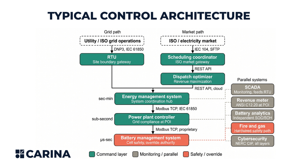
One architectural detail that most controls descriptions overlook: the site does not have one external communication path. It has two, and they are separate.
The grid operations path carries real-time telemetry and grid commands between the site and the external grid. Outbound, the RTU transmits telemetry: MW, MVAR, voltage, frequency, breaker status, and alarms. For BESS specifically, many ISOs also require real-time state-of-charge and available energy capacity as telemetry points. CAISO, for example, requires instantaneous SOC and Maximum Continuous Energy limit as part of its direct telemetry specification for non-generator resources, and these data points factor into the ISO’s dispatch decisions and the scheduling coordinator’s end-of-hour SOC bid parameter. This means the BMS’s SOC calculation propagates through the EMS, SCADA, and RTU all the way to the ISO’s dispatch algorithms, and any SOC estimation error at the BMS level creates real consequences at the market level.
Inbound, the site receives AGC regulation dispatch signals from the ISO, voltage regulation setpoints from the transmission owner, and curtailment orders from either. The protocols are DNP3 or IEC 61850. The RTU is physical hardware, typically located at the project substation, and is usually part of the EPC scope or the controls integrator scope.
The specific communication architecture for this path varies by ISO and by interconnection arrangement. In some configurations, the RTU communicates directly with both the transmission owner’s SCADA master and the ISO’s operations systems. In others, the RTU communicates with the transmission owner, and the ISO receives data through the utility’s infrastructure via inter-control-center protocols. AGC signals may arrive through the RTU, through a dedicated ISO communication link, or through the utility as a pass-through.
The developer’s interconnection agreement with the transmission owner and the market participation arrangement through the scheduling coordinator each have their own communication requirements, and the developer should confirm the specific telemetry routing and protocol requirements for both during the interconnection process rather than assuming a single standard architecture.
The market path runs from the dispatch optimizer through the scheduling coordinator to the ISO’s market system. This is the commercial and financial interface. Bids, schedules, settlement data, outage declarations, and resource registration flow through this path. The protocols are IEC 104, SFTP, or ISO-specific portals. The scheduling coordinator is almost always an independent firm or the owner directly.
These two paths serve different functions (real-time grid operations vs. commercial market participation), use different protocols, and are governed by different contracts (the interconnection agreement vs. the market participation agreement). The developer needs to understand both because they show up in different scopes, are tested separately during commissioning, and fail independently. A project can have perfect market communication while the RTU fails to report telemetry, or vice versa.
Several systems sit alongside this hierarchy rather than inside it. The fire and gas detection system operates through hardwired safety paths that are architecturally separate from the EMS command chain. Cybersecurity controls (NERC CIP classification, access management, network segmentation) thread through every layer. The data historian provides long-term storage and compression for operational data, feeding performance reporting and warranty enforcement.
A category that deserves particular attention is battery analytics and independent state-of-charge verification. Platforms like Accure, Twaice, and Zitara consume BMS, EMS, and SCADA data on a read-only basis and run independent physics-based or AI/ML models to produce their own SOC and state-of-health (SOH) estimates, degradation tracking, and anomaly detection. These platforms are not part of the real-time command hierarchy. They do not issue commands to the battery. But they solve a problem that matters to every developer: the OEM’s native BMS is the only real-time SOC source in the controls stack, and for LFP chemistry specifically, the flat open-circuit voltage curve makes BMS coulomb-counting unreliable. SOC estimation errors of 5-10% are common without periodic recalibration. A 5% SOC error in either direction means the dispatch optimizer is either leaving usable energy in the battery or bidding capacity the system cannot deliver. Independent analytics platforms claim to reduce that error below 2%.
More importantly, they give the owner an independent data source for warranty enforcement, because when a degradation dispute surfaces in Year 5, the owner does not want the only SOH evidence to come from the OEM whose guarantee is on the line. Whether these platforms can function at all depends on a procurement decision: the supply agreement must grant the owner access to cell-level data at sufficient granularity for third-party analysis. We will return to this point later.
Two principles govern the entire stack:
Commands flow down; safety overrides flow up. The dispatch optimizer sends a setpoint to the EMS. The EMS issues it to the power conversion system. The BMS validates that the command is within the safe operating envelope and executes. If the BMS detects an unsafe condition, it opens contactors and overrides everything above it. This bottom-up override authority is non-negotiable and must be preserved regardless of which EMS or optimizer is in the command path.
Safety actions must occur locally; software makes them visible. Fire detection, E-Stop logic, and BMS contactor isolation operate through hardwired paths that do not depend on the EMS being online, SCADA being connected, or the network being intact. The EMS and SCADA make those events visible, auditable, and operationally actionable. But the physical protective action must not require a software command to traverse the network to execute.
What Comes Bundled vs. What You Procure Separately
Not every layer in the stack is a separate procurement decision. Some are inseparable from the OEM product. Others are always independent. Several sit in a contested middle zone where the OEM offers a native solution but the developer may prefer, or need, a third-party alternative.
The BMS has historically been inseparable from the OEM. It is proprietary, integral to the battery product, and tightly coupled to the warranty. That is beginning to change. Third-party BMS solutions are emerging, driven by cybersecurity concerns (eliminating Chinese-origin BMS firmware and chips as a potential attack vector) and FEOC domestic content requirements.
Fractal EMS, partnering with Gold Electronic Equipment, now markets a US-made 3-level BMS (module, rack, system) with American-sourced chips and software, and positions it as a hardware-agnostic alternative to the OEM’s native BMS. This is still early. Replacing the OEM’s BMS raises warranty and safety liability questions that are more consequential than replacing the EMS, because the BMS is the safety-critical system that protects cells and controls contactors.
Most developers will continue to use the OEM’s native BMS for the foreseeable future, but the forces driving third-party alternatives are structural, and the developer should be aware they exist. PCS-level protection firmware remains non-negotiable. The site-level EMS is usually bundled as well: the OEM’s native controller is the default, and replacing it with a third-party system requires careful negotiation around warranty boundaries. SCADA may be part of the OEM’s EMS package or may be supplied separately by the EPC or a controls integrator.
The PPC is frequently independent, particularly for transmission-connected projects where the grid operator requires a dedicated, prequalified controller for frequency response and voltage regulation. The dispatch optimizer occupies an increasingly competitive space. OEMs like Tesla (Autobidder), Wartsila (IntelliBidder/GEMS), and Fluence (Mosaic) offer native optimization engines, but independent optimizers (Ascend SmartBidder, Equilibrium, Habitat, GridBeyond, Stem, among others) compete on revenue performance and market coverage.
The scheduling coordinator, the entity that submits bids and manages settlement with the ISO, is almost always an independent firm (Tenaska, Customized Energy Solutions, Boston Energy Trading and Marketing) or the owner directly.
The RTU, the revenue meter, and the fire and gas detection system are always independent of the OEM. The RTU is typically part of the EPC scope or supplied by a controls integrator, configured to the utility’s points list obtained through the interconnection management scope. The revenue meter conforms to utility and ISO specifications. The fire system is a separate life-safety installation with its own panel, backup power, and supervised wiring.
This bundling spectrum matters because the developer’s most dangerous assumption is that “the OEM handles controls” when the OEM’s scope actually ends at the site controller. The dispatch optimizer, scheduling coordinator, revenue metering, fire system integration, and cybersecurity compliance sit outside that scope. If the developer has not assigned those functions to someone, they belong to no one, and the gap will surface during commissioning.
Where the major OEMs fall on this spectrum varies. Tesla strongly favors its native stack: Megapack ships with a Tesla site controller, Powerhub provides monitoring and SCADA-like functions, and Autobidder handles dispatch optimization and market bidding. Third-party integration at the plant or market level is possible (Fractal has documented architectures where Fractal provides the master plant controller while Tesla’s site controller distributes commands to Megapacks), but the Tesla ecosystem rewards staying inside it. Fluence takes a more open approach: its OS7 platform handles system control and safety, while Nispera covers asset performance management and Mosaic handles bidding.
External EMS integration is explicitly supported through DNP3, Modbus TCP/IP, OPC-UA, and APIs. Sungrow bundles its EMS3000 with the PowerTitan product line; third-party controls are typically defined at the plant or POI layer, with Sungrow retaining equipment-level protection. Wartsila pairs its GridSolv Quantum hardware with the GEMS Digital Energy Platform, offering strong vertical integration from forecasting through real-time control and fleet-level visibility. GEMS is also designed to support multi-vendor battery hardware, making it relevant for mixed fleets. BYD supplies highly integrated battery and system blocks with embedded BMS and protection, but third-party upper-level EMS and integrators are commonly used for the plant controller and market interface. CATL’s EnerC product line supplies the battery container and BMS/safety architecture, with the upper-level EMS frequently provided by the system integrator or controls partner (FlexGen’s HybridOS is a documented example).
The Three Decisions That Shape the Controls Architecture
Three strategic choices during procurement determine the controls architecture. Each one has consequences that persist through the operating life of the project.
Native EMS vs. Third-Party EMS
The first decision is whether to accept the OEM’s native EMS as the command layer or to insert a third-party EMS above it in a “leader/follower” configuration.
The warranty implications drive this decision more than anything else. Using a third-party EMS does not automatically void the OEM warranty, but some OEMs impose conditions that make it difficult in practice. Tesla, for example, requires its own site controller to remain in the command path and tightly restricts external access to BMS data and control interfaces. Other OEMs may require that any third-party controller be explicitly approved and tested against the OEM’s integration specifications before the warranty will be honored.
The developer should not assume that “third-party EMS compatible” in a marketing brochure means the warranty will survive the substitution without negotiation. The OEM’s written position on third-party integration, including which APIs and register maps are exposed, which functions remain closed, and what approval process applies, must be obtained during technology selection, not after the supply agreement is signed.
Beyond access, the OEM’s performance guarantees for availability, round-trip efficiency, and degradation may be conditioned on its native control modes and operating parameters. If the third-party EMS operates outside those parameters, even briefly, the burden of proving that no damage occurred shifts to the owner.
Data custody is the counterargument. A native EMS means the OEM records all operational data, including data about its own faults. When a degradation guarantee dispute arises years into operations, the owner’s only SOH evidence comes from the OEM’s own BMS. Independent battery analytics platforms (Accure, Twaice, Zitara) address this by running physics-based models against the raw BMS data to produce independent SOC and SOH calculations.
But these platforms can only function if the supply agreement grants the owner access to cell-level voltage, temperature, and current data at second-level granularity, not just aggregated container-level summaries. This data access provision is a procurement decision, not something to negotiate after the contract is signed.
For owners operating multiple BESS sites from different OEMs, a vendor-neutral EMS may be necessary to provide a unified dispatch and monitoring interface across the fleet. This is a legitimate operational requirement, not just a preference, and it should be established during OEM evaluation rather than retrofitted afterward.
OEM Dispatch Optimizer vs. Independent
The second decision is whether to use the OEM’s native bidding and optimization engine or to procure an independent dispatch optimizer.
Revenue performance is measurable and competitive. Dispatch optimizers compete on percent-of-perfect capture, and benchmarking services (Modo Energy publishes the most widely referenced data) show meaningful variance in optimizer performance within the same ISO. The developer should evaluate an optimizer’s track record on actual operating assets, not just the OEM’s marketing claims.
Vendor lock-in is a real consideration. An OEM dispatch optimizer ties the project’s revenue performance to a single vendor for the life of the project. If the optimizer underperforms or the project needs to switch markets, the switching cost may be substantial. Market coverage also matters: not all OEM optimizers cover all ISOs. Tesla Autobidder has a strong position in ERCOT and CAISO. Fluence Mosaic covers ERCOT, CAISO, MISO, and international markets. A project in ISO-NE, NYISO, or SPP may need an independent optimizer regardless of the OEM.
The commercial structure of the optimizer engagement varies. Three models are common: tolling (a fixed fee; the optimizer manages the asset and keeps revenue above the toll), merchant or profit-share (the optimizer and the owner split optimization revenue on an agreed ratio), and SaaS (a subscription fee for non-binding bid recommendations). The commercial model affects risk allocation and should be evaluated alongside technical performance.
The Modo Energy taxonomy for the US market is useful here. In ERCOT and other ISOs, the functions are divided into three categories: QSE services (the scheduling entity that handles physical operations, monitoring, and ISO communications), DME services (the entity that makes commercial dispatch decisions), and auto-bidder services (the algorithmic engine that generates non-binding bid recommendations). Some firms provide all three (CES, Equilibrium, GridBeyond, Tesla). Some provide only the scheduling function (Tenaska). Some provide only the optimization engine without scheduling (Tyba).
The developer needs to understand which functions a given vendor covers and which require a separate engagement.
Single-Vendor Integration vs. Multi-Vendor
The third decision is whether to have one party own the full controls integration scope or to distribute controls responsibility across multiple vendors.
The single most common source of controls integration failure is that no single party owns the end-to-end test from ISO command to POI response. In a multi-vendor architecture, each party tests its own component. The OEM tests the BMS and PCS. The EMS vendor tests the EMS. The EPC tests the electrical systems. But no one tests the interfaces between them. When the plant fails a grid-code compliance test or misses a market dispatch, the question of who is responsible has no contractual answer.
The developer can mitigate this by assigning a single party (the EPC, the controls integrator, or the OEM) as the integration lead with contractual accountability for end-to-end performance. The controlled documents that define the interfaces (the interface control document, the complete point list, the command-priority matrix, the alarm and cause-and-effect matrix, the communications network diagram, the time-synchronization architecture, and the operating-envelope/warranty matrix) should be contractual deliverables, not informal coordination artifacts. The integrated functional test protocol should be defined in the EPC scope before the RFP is issued, not negotiated during commissioning.
Fire Safety as a Controls Scope
Most developers think of fire safety as a fire code and AHJ compliance scope. In practice, the fire safety system is deeply integrated with the controls stack, and the integration between the two is where real incidents originate.
Fire detection and E-Stop logic operate through hardwired safety paths that are architecturally separate from the EMS command hierarchy. The fire-and-gas panel receives inputs from off-gas detectors (VOC, CO, hydrogen, LEL sensors), smoke detectors, heat detectors, and flame detectors. When a threshold is reached, the panel executes hardwired trip logic: BMS contactor isolation, PCS gate inhibit, HVAC shutdown or controlled purge, suppression sequence, and alarm outputs.
The EMS receives the alarm, aggregates it, blocks dispatch, marks the affected equipment unavailable, and propagates the alarm to SCADA and the remote operations center. But the EMS does not initiate the safety action. A loss of EMS, SCADA, or network connectivity must not prevent a local fire trip.
The developer should be able to trace the complete signal path during design review and commissioning: sensor activation, fire/gas panel response, local audible and visual alarm, BMS contactor isolation and PCS inhibit through hardwired connections, EMS alarm aggregation through the network, SCADA and ROC notification, external responder notification, E-Stop and AC/DC isolation, restart lockout, authorized reset, and post-event monitoring. Every link in that chain is a potential integration failure point.
The most common fire/controls integration failures are well documented across the industry: fire-panel alarm points mapped with reversed normal/fault states in SCADA; alarms displayed locally but not forwarded to the remote operations center; BMS trips that open contactors but do not block PCS restart; E-Stop reset logic that differs between the fire panel and the EMS, preventing recovery; maintenance or offline modes that defeat protection without a visible indication at the ROC; and the absence of a common time source across BMS, fire panel, and SCADA, making post-event sequence-of-events reconstruction unreliable.
The Victorian Big Battery incident in Australia is the canonical case study. The independent investigation found that the affected Megapack had been placed into an offline service mode during commissioning that disabled telemetry and removed visibility at the control facility. The battery’s high-voltage controller and protection system were also shut down. The developing fault went undetected because monitoring and protection had been silently defeated.
The lesson is specific: no commissioning, maintenance, or offline mode should silently defeat required protection, fire detection, telemetry, alarm forwarding, or event recording. Every bypass mode needs a visible local and remote indication, an alarm at the ROC, authorization and timeout controls, and an explicit statement of which protections remain active.
In our development process, we treat fire safety integration as part of the controls scope, not as a separate fire-system checkout. Our fire protection engineering scope includes a coordination memo that defines the interface between fire safety systems and the electrical and controls architecture: shunt-trip and emergency shutdown logic, “keep-alive” circuit isolation for gas detection and ventilation, and the cause-and-effect matrix that maps each initiating condition to its required protective action.
Our BESS Owner’s Engineering scope includes verification that the OEM’s SCADA architecture incorporates off-gas detection alarm points on the site points list, automated trip logic that can execute contactor isolation without operator intervention, and event logging for off-gas detection events. These are not separate disciplines working in parallel. They are coordinated through explicit interface gates in the project plan.
The Revenue Meter: The Source of Truth
The revenue meter is not a “controls” system in the traditional sense. But it is the single most important measurement in the entire stack for the developer’s financial outcome, and its relationship to the EMS, the dispatch optimizer, and the ISO settlement system is a scope boundary that creates real problems when it is misunderstood.
The revenue meter sits at or is electrically compensated to the point of interconnection. It conforms to ANSI C12.20 (0.2% accuracy class is typical for transmission-level connections) and provides bidirectional active energy measurement (MWh delivered and MWh received), instantaneous MW and MVAR, interval registers, and time-stamped event logs. It is not a software function inside the EMS. It is a separate certified instrument, and the ISO settles the project using the designated meter of record, not the EMS’s internal calculations.
There will always be a gap between what the EMS thinks the project delivered and what the revenue meter measured. Transformer losses, auxiliary loads (HVAC, fire systems, lighting, station service), cable losses, and metering error all create a delta. The developer should design for a formal meter-data reconciliation process from the start: revenue-meter interval MWh compared against SCADA MW integration, PCS AC energy, BMS DC energy, auxiliary consumption, and transformer losses. Unexplained differences are a commissioning and commercial risk that compounds over time.
Meter ownership varies by interconnection arrangement. The utility may own and maintain the revenue meter. The project may own a meter that the utility approves and seals. The project may provide the metering equipment with ownership transferring to the utility after commissioning. What matters is that the contract explicitly identifies the meter owner, the meter of record, the testing authority, the calibration interval, and who bears settlement risk. The revenue meter does not care what the EMS intended. It measures what the POI actually delivered.
Cybersecurity and Grid Compliance Standards
Two regulatory frameworks shape the controls architecture in ways the developer must address before the EPC RFP, not after.
NERC CIP classification (Low, Medium, or High Impact) is determined by the Transmission Provider and defines the physical and cyber security compliance requirements for the project’s control systems. The classification affects firewall architecture, access controls, remote access policies, logging requirements, and patch management. The RTU is a particularly important NERC CIP boundary: it is the physical device that crosses the network perimeter between the site and the utility’s grid operations systems, and the firewall and access architecture around it must reflect the classification. Retrofitting NERC CIP compliance into a controls architecture that was designed without it is expensive and disruptive.
In our development process, NERC CIP classification is obtained through the interconnection management scope and fed into the SCADA/EMS definition before the controls architecture is finalized.
IEEE 2800 is the emerging standard governing the performance and interconnection requirements for inverter-based resources, including BESS. It defines how the PPC must behave during grid disturbances (frequency response, voltage ride-through, momentary cessation and recovery) and includes commissioning test requirements that verify the installed plant meets those obligations. Utilities and ISOs are increasingly requiring IEEE 2800 compliance as a condition of interconnection. The developer should confirm which version the interconnection agreement references and ensure the PPC vendor’s product is prequalified.
How We Handle This in the Development Process
The controls architecture touches nearly every discipline in a BESS development engagement. Rather than treat controls as a single procurement line item, we address it through a sequence of scope gates that correspond to the natural progression of the project from technology selection through commissioning.
During technology selection, when the developer is evaluating OEMs through a technical RFI, we query each OEM on EMS architecture, native vs. third-party compatibility, available dispatch modes, SCADA interface protocols, telemetry capabilities, and BMS override behavior. We also query the OEM’s position on third-party controls integration and its warranty implications. For the OEMs that advance to the RFP stage, this information feeds into the technical specification and the bid evaluation. The controls architecture is not evaluated in isolation; it is assessed alongside the OEM’s UL 9540A test data, degradation guarantees, and augmentation provisions, because all of these interact.
When we define the SCADA and EMS requirements for a project, we verify the OEM’s proposed capabilities against the interconnection agreement and the project’s market participation requirements. We confirm dispatch modes, obtain the utility’s SCADA interface requirements through the interconnection management scope, define the points list, verify communication protocols, incorporate NERC CIP classification, and verify that off-gas detection alarms are integrated on the SCADA points list. This is also where we confirm that the fire protection engineer’s E-Stop and emergency shutdown logic is reflected in the controls architecture, not just in the fire protection drawings.
At the supply agreement stage, the technical exhibits define the operating envelope, response time requirements, commissioning support expectations, and the warranty responsibility matrix. This is where data access provisions for independent analytics must be secured: cell-level voltage, temperature, and current data at second-level granularity, with the right to export to third-party platforms. If the OEM restricts data access to aggregated dashboards on its own portal, the owner loses the ability to run independent SOC/SOH verification and is dependent on the OEM’s reporting for both performance evaluation and warranty claims.
The EPC scope definition is where controls integration risk either gets managed or gets deferred to commissioning. We include the interface control document, command-priority matrix, and test responsibility matrix as contractual EPC deliverables. We define end-to-end integrated functional testing as an EPC scope item, distinct from component-level testing. We specify time synchronization architecture (NTP/PTP) across all systems and define the revenue-meter integration and reconciliation test.
The RTU is a frequent source of scope gaps: the EPC assumes the controls integrator or the OEM will configure it, while the controls vendor assumes the EPC will supply and wire it. We define the RTU scope explicitly in the EPC RFP, including the utility’s points list (obtained through the interconnection management scope), the SCADA-to-RTU data mapping, and the communication link to the utility’s grid operations center.
During commissioning itself, the test we care about most is not whether every device responds to a local command. It is whether an external command or market signal travels through every required interface, produces the correct physical action at the POI, is measured by the revenue meter, is visible to the remote operations center, and fails into a defined safe state when any intermediate system is unavailable.
We test all safety paths end-to-end: from sensor to fire panel to BMS isolation to EMS alarm to SCADA notification to first-responder dispatch. We test failure modes: loss of EMS, loss of SCADA, loss of wide-area network, loss of POI meter, stale BMS data. We verify that no commissioning or maintenance mode silently defeats protection, fire detection, or alarm forwarding.
We test the RTU path separately: point-by-point verification of every telemetry point the utility and ISO expect, CT/VT ratio and polarity confirmation, incoming AGC signal tracking from the ISO, and failover behavior when the communication link drops. And we test the scheduling coordinator and ISO market handshake: resource registration, bid-to-dispatch-to-POI response, outage declarations, and meter-data submission.
The plant is controls-complete when that end-to-end proof exists, not when the EMS screen shows green.
Conclusion
The controls stack is not a single system that a single vendor owns. It is a collection of systems with different vendors, different contracts, different protocols, and different timescales, all of which must work together from commercial operation through the end of the project’s useful life. The developer’s role is not to design these systems. It is to understand the boundaries well enough to manage the scope, hold the right parties accountable, and insist on end-to-end proof before accepting the plant.
Authority boundaries between systems must be defined during design, not discovered during commissioning. The fire safety system is a controls scope, not just a fire code scope. The revenue meter is the source of truth for the project’s economics. And the single most valuable controlled document in the entire process is the one nobody wants to own: the interface control document that maps every handoff between every vendor in the controls stack.
The developer who can read this stack and ask the right questions during procurement will avoid the commissioning problems that cost schedule, revenue, and sometimes safety.
References
- Carina Energy, BESS Owner’s Engineer Scope of Work. The following tasks informed this article:
- BOE-100: Technology Selection and Design Basis (Phase 100). OEM Technical RFI including EMS architecture, off-gas detection architecture, SCADA data access, and telemetry capabilities.
- BOE-310: 30% Design Review and Interconnection Support (Phase 300). Design review of civil and electrical IFB packages for FPE integration, E-Stop isolation logic, and model data coordination with GRD.
- BOE-320: SCADA and EMS Definition (Phase 300). Verification of OEM-proposed control system against operational, utility, and cybersecurity requirements; off-gas detection integration; cyber-hardening for NERC CIP.
- BOE-395: BESS Technical Specification Development (Phase 300). Owner’s binding technical requirements for the BSA/LTSA including performance specification, commissioning support requirements, and response time requirements.
- BOE-396: BESS RFP Support and Bid Evaluation (Phase 300). Technical bid sheet, Division of Responsibilities matrix, qualified bidder list, and technical compliance scoring.
- BOE-400: BSA/LTSA Technical Review (Phase 400). Technical exhibit redlines and gap analysis.
- BOE-410: EPC Contractor Technical Evaluation (Phase 400). EPC prequalification criteria, RFP technical exhibits, and proposal evaluation.
- BOE-500: Commissioning Support and Testing (Phase 500). Commissioning plan review and performance test witnessing.
- Carina Energy, Fire Protection Engineer Scope of Work. The following task informed this article:
- FPE-310: Civil and Electrical Systems Integration Memo (Phase 300). Defines the interface between fire safety systems and the electrical/controls architecture: E-Stop shunt-trip scope, “Keep-Alive” circuit isolation for gas detection and ventilation, water supply requirements, unit spacing, exclusion zones, and off-gas detection system integration instructions for the Electrical EOR and BOE.
- Carina Energy, Interconnection Manager Scope of Work. The following task informed this article:
- GRD-315: NERC CIP and Security Requirement Definition (Phase 300). Classification inquiry with the Transmission Provider, utility substation physical security standards, and cyber interface requirements for RTU/SCADA. Deliverable: NERC CIP Security Design Basis Memo issued to ELC and BOE.
- Carina Energy, Electrical Engineer Scope of Work. The following tasks informed this article:
- ELC-300: Electrical Engineering and BESS Integration, 30% Design (Phase 300). Single Line Diagram incorporating shunt-trip and isolation requirements from FPE-310, emergency shutdown coordination with “Keep-Alive” circuits, interconnection consistency review with GRD, and auxiliary power/Station Service load analysis and transformer sizing from BOE-300 inputs.
- ELC-320: Security Systems Design (Phase 300). NERC CIP security systems design triggered by GRD-315 Security Design Basis Memo.
- Drew Lebowitz, Sean Daly, and Swetha Meenakshi Sundaram, The BESS Book, Chapters 5 (BESS Controls), 7 (Project Finance), and 9 (Operations and Maintenance).
- PowerKonnekt, “4 BESS Control Systems Explained: EMS, BMS, SCADA, PPC,” May 2026. powerkonnekt.com/articles/ems-vs-bms-vs-scada-vs-ppc
- Modo Energy, “US Battery Energy Storage Operators and Optimizers,” April 2025. modoenergy.com/research/en/battery-energy-storage-optimizers-operators-usa
- Energy Safe Victoria, “Victorian Big Battery: Statement of Findings,” September 2021. energysafe.vic.gov.au (PDF)
- Nor-Cal Controls, “The Benefits of Using a Single SCADA for PV and BESS,” August 2025. norcalcontrols.net
- Nor-Cal Controls, “Understanding the Main Plant Controller,” July 2024. blog.norcalcontrols.net
- Fluence, “Gridstack Technical Specification” (OS7 platform). fluenceenergy.com (PDF)
- Fluence, “Fluence OS Overview.” fluenceenergy.com (PDF)
- Wartsila, “GEMS Digital Energy Platform.” wartsila.com
- Tesla, “Autobidder: Autonomous Energy Trading.” tesla.com
- Tesla, “Tesla Software for Energy Products.” tesla.com
- Fractal EMS, “Tesla Megapack Integration Architecture” (RE+ 2024 presentation). PDF via rxweb
- Sungrow, “EMS3000 Energy Management System.” sungrowpower.com
- Sungrow, “Third-Party Compatibility Overview.” sungrowpower.com (PDF)
- CATL, “FlexGen and CATL Announce Strategic Cooperation” (HybridOS + EnerC). catl.com
- Accure Battery Intelligence, “SOC Accuracy for BESS.” accure.net
- CAISO, “Metering and Telemetry Requirements.” caiso.com
- PJM, “Manual 14D: Generator Operational Requirements.” pjm.com (PDF)
- EPRI, “Energy Storage Integration Council (ESIC) Commissioning Guide,” Report 3002027455. epri.com
- NERC, “Reliability Guideline: BESS and Hybrid Performance, Modeling, and Studies.” nerc.com (PDF)
- IEEE 2800-2022, “Standard for Interconnection and Interoperability of Inverter-Based Resources (IBRs) Interconnecting with Associated Transmission Electric Power Systems.” standards.ieee.org
- EASE (European Association for Storage of Energy), “Guidelines on Safety Best Practices,” May 2025. energystorageeurope.eu (PDF)
- Power Factors, “EMS and SCADA for One of the World’s Largest Solar-Plus-Storage Projects,” August 2024. powerfactors.com